 Mike Karthauser.
Bucket Placer
A TypeScript lab for Daihatsu Copen JB-DET engines: reuse worn shimless cam buckets when replacement sizes are no longer available, by measuring true centre thickness and placing the best 16 from a pool of up to 32 against cold intake and exhaust clearances.
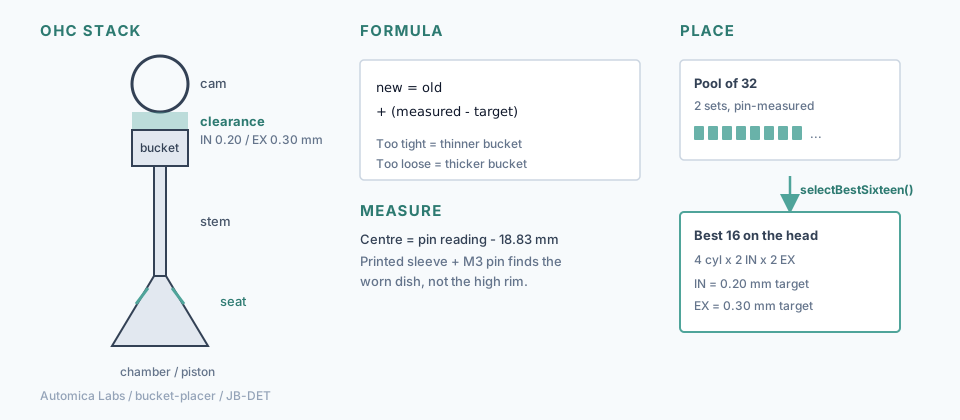
Why this exists
The first-generation Copen and its JB-DET kei engine are long out of production. Specific cam-bucket thicknesses are hard or impossible to buy new. When rebuilding a head, you cannot rely on a dealer parts list for an obsolete car.
Bucket Placer turns scrap and spare-engine stock into a measured pool: ignore misleading side stamps, record centre thickness, then pick and place the best 16 against real cold clearances.
How wear happens
Each bucket sits between a cam lobe and a valve stem tip. The lobe dishes the cam face over time:
- Early wear is centred. A flat micrometer bridges the dish and reads the high rim, so the face looks thicker than it is.
- Later wear can take the whole pad down so rim and centre converge. Exhaust runs hotter and often wears faster.
- Heat and oil problems (for example after a head gasket failure) can wipe the face more broadly than a neat centre dish.
The side stamp is the factory thickness code. Once worn, it is historical. Placement must use measured centre thickness. Lapping valves recesses them into the head and tightens clearance, which often makes thinner worn buckets useful again after a valve job.
Two full sets (32 buckets) from a pair of engines, one with a head gasket failure, are the working stock once every bucket is measured at the centre.
Why the pin guide matters
A flat micrometer sits on the high rim of a dished face and overstates thickness. The OpenSCAD sleeve drops into the bucket and holds an M3 bolt of known length (18.83 mm tip to top of head) so the tip finds the centre of the pad. Centre thickness is the micrometer reading minus that pin length.
That fixture is what makes the catalogue trustworthy: every bucket is measured the same way at the wear point that actually sets clearance, not at the rim. On set 1, many buckets looked about 3.4 mm on the rim while the centre sat near 3.0 mm.
Cold valve clearance
Clearances are checked cold, with different targets for each side of the head:
- Intake: 0.20 mm (allowed 0.17–0.25 mm)
- Exhaust: 0.30 mm (allowed 0.27–0.35 mm)
Daihatsu selection formula
With any 16 buckets installed and the cams fitted, measure each gap, then compute the thickness that would hit the target:
new thickness = installed thickness + (measured clearance − specified clearance)
- Gap too small: choose a thinner bucket
- Gap too large: choose a thicker bucket
Lapping valves recesses them into the head and tightens clearance, so thinner worn stock often becomes useful after a valve job.
Workflow
- Catalog – stamp, rim reading, and pin reading in
cam-buckets.ts(keys like1:A,2:Pacross two sets). - Measure centre – 3D-printed sleeve guides an M3 pin (18.83 mm); centre = reading − pin length.
- Trial fit – install any 16, fit cams, record cold gaps per port (4 cylinders × 2 intake × 2 exhaust).
- Place –
selectBestSixteen()picks the closest matches from the full pool; leftovers stay as spares.
Repository layout
Core
cam-buckets.ts– inventory, pin math, clearance constantsassign-buckets.ts– port map andselectBestSixteen()tests/formula.test.ts– formula and assignment tests (Vitest)
Hardware helper
bucket-measure-sleeve.scad– OpenSCAD guide so an M3 pin finds the dish centrebucket-measure-sleeve.3mf– ready-to-print export- Pin length 18.83 mm; centre = reading − pin